Resuming the blog!!!

Posted: August 6, 2015 in Pathfinder

Hello Guys!

After 2 years and more of here and there, trapped by all kind of stuffs, I think it is high time that I resume my blogging. Going to the senior year of Engineering, I have obviously learnt a lot and i can not wait to try more cool stuffs that comes around. I will start off with some projects and new ideas that i can come up with and will definitely put in some efforts in restructuring this blog!

Lets create something!

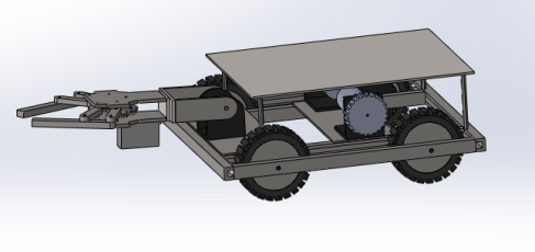
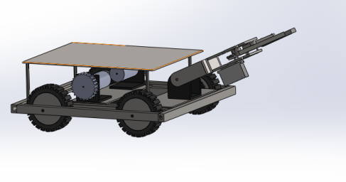
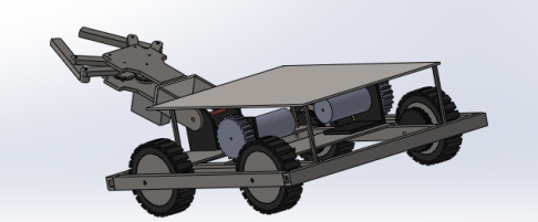
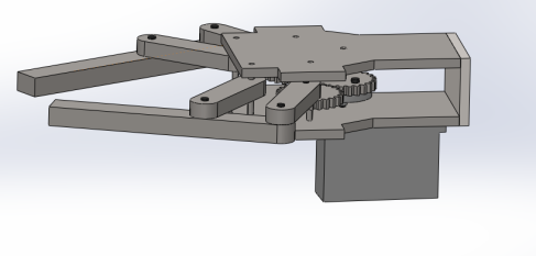
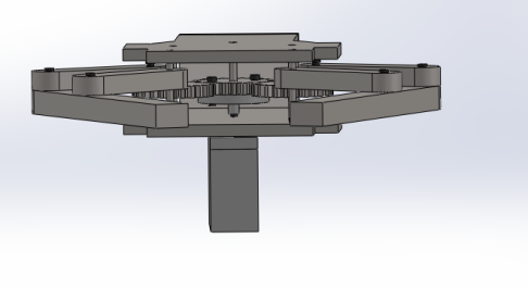
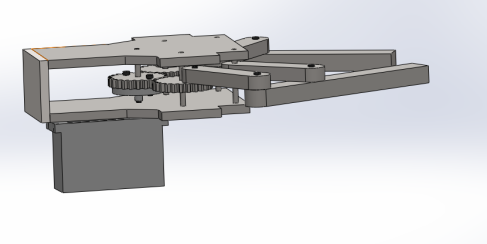
It has been almost a week since I started working with SolidWorks. It is  so much fun when You can make a 3D model of what you want. Continuing my design for the robotics competition I made a gripper for my robotic arm. Pretty tricky than previous stuffs I had done. Although I still can not do simulations in SolidWorks and will come up with a video as soon as I learn Simulation part. Here are some pictures regarding the new gripper design. It was my first time making a mechanical part which was pretty tough. I hope my calculations were right and it works fine when I make it a few weeks may be.

ImageImageImageImageImageImageImage

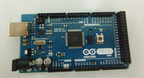
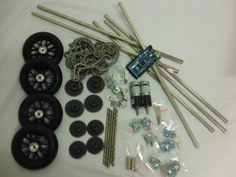
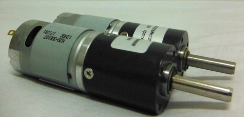
I recently started working on a new project. Its more like making bots for a robotics competition to be held in near future. Pretty big lets say. Thanks to my generous college who has agreed to fund me(its actually a team of 5 people). First it was the general designing part which I did it solidworks. I uploaded some pictures in a  post regarding my designs made using solidworks. Now its time to make the bots. This weekend Me and one of my team member visited one of the biggest electronics market around Bangkok, “Baan Moh” well its very hard for me to spell it since its a Thai name. We wanted to start with making the bigger bot first which would be a manually controlled bot. Big and heavy this would require really good amount of hard work to complete it. Well, we got some basic stuff for making the base part of the manual bot which would include its locomotion. Here are some pictures of the parts we got. We spent like 200$ for all these! Not so cheap!One of the most wanted stuff for me that I got with these was the Arduino Mega 2560. Using Arduino Uno for almost a year I wanted to go one step up and make bigger project using its brother Arduino Mega. And hopefully this project will complete my wish.

Image

Arduino Mega 2560

Image

All stuffs kept together

Image

14 cm diameter and 6 mm shaft hole Tyre which can withstand high pressure

Image

12v Dc motors to be used in belt drive system to make a locomotive base

Image

Gears to be used in belt drive system.

Image

Well, obviously there will be more parts to be bought and lot more stuffs to be handled. For now assembling and testing all these will keep me busy for a week? Hope so

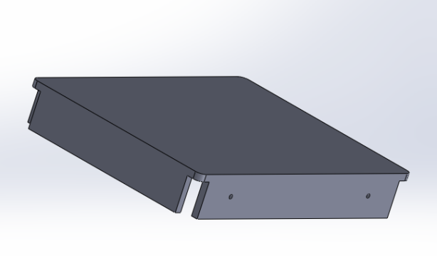
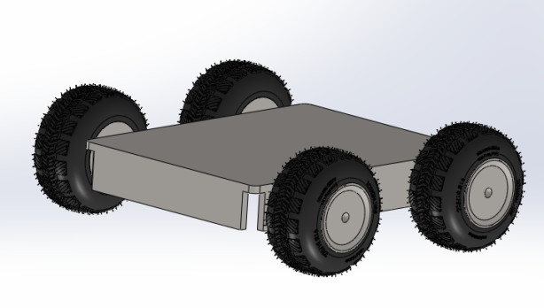
I decided to make a new design for mobile base. With my team on we decided to drop the plate on bottom we had on previous design. We also outlined general drive techniques for 4 wheels. Its always fun working on Solidworks and this finally moving on with more complex design, However I am still working on making chain that connects drive shaft gear and gear attached to the wheels.

ImageImageImageImageImage

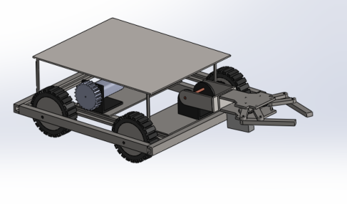
I found some free time and decided to improve infact build up more of what we are trying to make for the competition. I figured may be improve the wheel base robot ? Few mugs of insane caffeine and finally I could come up with something that looked like a arm(although the things looks still primitive with so less details)! The copper cube is supposed size of the autonomous bot that this manual is gonna carry. My team is still discussing the mechanisms for dropping the autonomous bot. The arm will be used to do task like picking of object around the arena. I will write a post about  more about details of both bots in near future, although even this design of manual bot is still a concept. However, I still could not make the perfect gear, end effector in the arm and belt drives so I left them for now.Anyway we all know how tortoise won against the rabbit!Slow and steady and that’s how I am gonna do!!
Here’s some snaps!

bad snap!

bad snap!

Solidworksv2

Solidworksv2

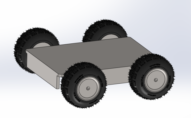
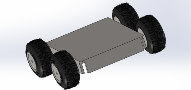
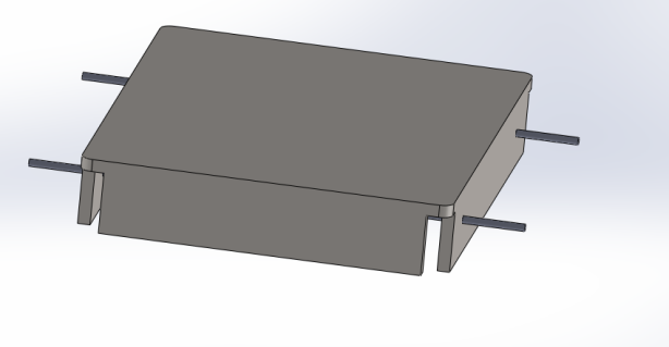
First Plan then do something!Designing robots,mechanical part,cars,plane was taken to whole next level when computer entered the world arena. Then started coming new software which would specialize in specific task. Likewise solid-works is basically a powerful software to design all these stuff and I was lucky enough to lay my hands on a licensed version(Thanks to my college!!). It had remained unused in my laptop for quite a while since I had not come across any serious projects. Recently, I started working for one robotics competition and its pretty huge. In an attempt to make a design I started using solid-works with my past memories of engineering drawing  and after quite a lot of help from seniors and fellow friends I was able to accomplish a basic design for base in one of the bots to be constructed. It would be unwise to go for a really complex design and me being a beginner here would make it almost impossible. So make why not make it simple !!Here is my first ever design in solid-works. I used the Tyre  designed by someone else  and just assembled it with my base. The link to the page for the Tyre used is (http://blogs.solidworks.com/teacher/2011/05/not-an-ordinary-tire.html). The Tyre I made was nothing more than a solid cylinder which did not quite felt like a Tyre so I switched into this idea. Although I was really happy when everything was assembled and some immature sketched finally turned into a model which would later be implemented to real life!!

base with fillets and holes drilled in for shaft

base with fillets and holes drilled in for shaft

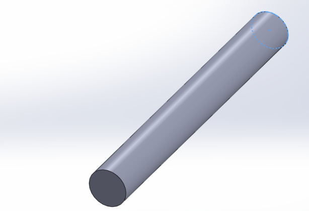
Shaft created as separate part

Shaft created as separate part

Snapshot of Design

Snapshot of Design

Another view

Another view

Model of my design

Model of my design

body with carbon steel and shaft attached

body with carbon steel and shaft attached

Open the door, go inside your room and lights go on its own,music in on.Open the curtain?..just push a button or just say “open curtain” and it does the work!Warmed up inside the blanket and you do not want to go out just to close the lights. Say “Close the lights” and lights go off!

While I was going through YouTube videos, I found this awesome video where a freshman in UC Berkeley makes his room as highly automated as possible. Sleep mode, Romantic mode, Party mode, a really great job done here. With tablets,smartphones and computers everywhere these days and increase use of robotics its not impossible to make a automated room if you have good enough knowledge in technology(gadgets, programming and bit of simple automation). As you can see in the video, he controls most of the things with smartphone, tablet and a computer using manual touch inputs or voice commands. Its really cool to see how the whole setup of the room could look different with one touch or on one voice command. Recently I wrote about a mood lamp which could be controlled through you android phone(https://techmaniacsgarage.wordpress.com/2013/06/22/why-mood-lampwhy-not-just-normal-lamp-make-a-arduino-mood-lamp/) Making your whole room automated is way harder then just making a lamp automated. But its worth a try though. There are whole lot of stuff to be found on Google(although i prefer to find more original ideas) and stuff you need like servos,dc motors, sensors, micro-controllers are everywhere these days. Not that hard to find them. I would definitely want a room like this which off course should be permitted by my college. Anyway, if you want to start then just start with simple stuffs first. Like getting inputs from motion sensor which is beside your door and detect as soon as someone comes in. Feed the signal to your micro-controller and ask it to perform certain task such as light a bulb. Moving a curtain would require in most cases pulling a string. Now that can be done with encoded dc motors or even with servos. You need to figure your ways of giving instructions to motors. Making a app for your smartphone, computer or tablet can be bit tricky and hard if you are not into making apps. Move through basics and reach as far as getting a cup of hot coffee in your hand with one command!!
If you are looking for cool projects for this summer then this might be a great idea. After all the hard work its definitely cool when you room becomes more like a Jarvis!!!

Video  —  Posted: July 8, 2013 in How to do stuffs!
Tags: , , , , , , , , ,

Why Mood Lamp?Why not just normal Lamp?The makers of this project had a great explanation supported by facts here. They presented that the fact that colors visible to human eyes could actually change the way we think or the present mood. For instance colors like red would give psychological response like anger, aggression, passion, pumped up kinda feeling. Colors like Blue would make it feel like the surrounding is clean and neat. Various psychological effects of colors have been noted and researched on and they actually work. When it comes to working in a dark room where you need some light or off course everybody of us will need light when the Sun goes down right? So far there are various versions of light ranging from Edison’s initial bulb to latest stuff  like CFL tubes which take in really low energy giving more light to the environment. So how cool would it be to actually change the color of light in case you might need a mood change or may be you just want to feel different. There is also special therapy known as Chomo therapy which uses light to deal with disorders or disease. Would it be more cooler and more interesting if any of your latest phones which has android can do it? Yes it would be and it would be totally amazing . This is what exactly these guys have made here.

Mood Lamo

Mood Lamp

Another awesome project here by Mik(Visutr Boonnateephisit) and Nidhi Adhikari following the end of second semester. The main aim here was to make a light(which in this case was set of LEDs) change color through you phone using a Arduino UNO as a microprocessor. One of the major development here was making their own Android app for this particular project. This app could on and off the light,control the intensity as well as the color saturation of the light using different combination of red , green and blue.

Interface of the app


Interface of the app

Interface of the app


Here is the video to Mood Lamp Randomization

As you can see above, the app is really good and even has a randomization mode when the auto switch is on. This mode constantly changes the color of the lamp in a random sequence.

Pretty handy for a decoration eh? Or you can manually control the combination of colors by selecting the particular saturation level. Clean,looks good as a decoration stuff as well, easily controlled though your phone via Bluetooth and gives you the right mood you need when you want it.

Here is the video of  the Mood Lamp Without finishing touches

This is one hell of a good deal. Major concept here is establishing wireless serial Plus this project is really low budget if you already have a arduino. Not more than 30-40$ depending on the material you are using. Major cash would go in to buying a microprocessor(if you do not have one) and in to buying a Bluetooth module for you particular microprocessor. Rest are not that expensive stuff. Major time would go into making  the app. Well, say what its already been developed and ready to use with installation file available. If you want it you can download  it from here(https://www.box.com/s/j49lzo0ouaqzks6o7uof)

To comment on it I would say that its a really good project to do in a free time when you are low on budget and you want more programming stuff to do. There are still lot of improvement that can be done with this project for instance may be when there is music in the house , we can take in the sound through a microphone analyze it and glow the lights accordingly. That would take a lot of work though. Plus you could further connect all the lights and control through a single arduino. In this project there is one Light only controlled through a single arduino.

More photos here(http://www.facebook.com/pages/Project-ML/519692344747941?id=519692344747941&sk=photos_stream)

Comment for further queries and thanks a lot for checking this out. Plus there is a Facebook page for this website where you can check out more stuff. Like it if you want more info!!!! Here is  the link(http://www.facebook.com/pages/Project-ML/519692344747941)
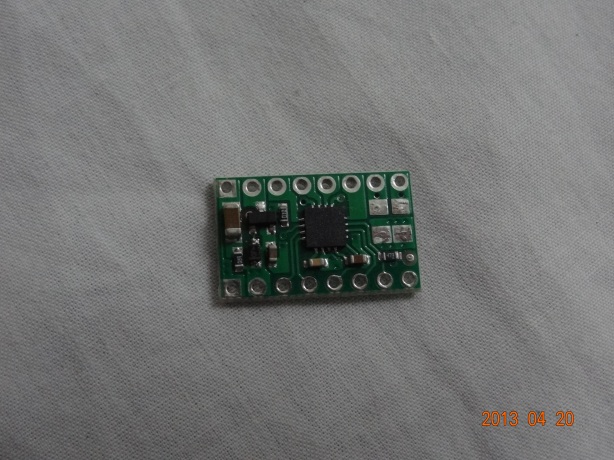
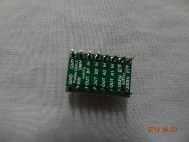
Hey guys, while working on our pathfinder robot(https://techmaniacsgarage.wordpress.com/category/pathfinder/) we were working with some pretty good motor drivers. We figured how to use it and now we will share how to work with it and arduino. Arduino is nodoubt one of the best in its class of microprocessor and works with wide variety of drivers.  DRV8833 Dual Motor Driver works clean with arduino. Below is a picture of the driver.

DRV8833 Dual Motor Driver Carrier

DRV8833 Dual Motor Driver Carrier

DRV8833 Dual Motor Driver Carrier (back view)

DRV8833 Dual Motor Driver Carrier (back view)

It has its own datasheet as well. You can refer to its company site for more detailed information(http://www.ti.com/lit/ds/symlink/drv8833.pdf). Moving on, let me share some basic ideas to work with this driver. Its one of the most easy one to use when you have low voltage low current motors to work with. As you can see in the above picture there are 4 out pins and 4 in pins. You can use first two “in” pin for input  from microprocessor you are using. The respective first two output pins will be for 1 dc motors. Same goes for the other two pins. Now, this driver does not need a enable pin. Its useful when you have problem with available number of digital pins. So for providing the GO signal to the driver, all you need to do is put one of the two input to HIGH and another to LOW. Suppose if the first two pins are connect to 4 and 5 in you microprocessor then your code should initiate pin 4 to send HIGH and 5 to send low. Same goes for another two input pins. You can use slow decay and fast decay as well through this driver. You can refer to datasheet for that. Now, for the voltage do no supply more than its rated voltage. There are two ground pins. So you can connect ground to either of them and the positive to VIN pin. This will do the work of supplying power to two dc motors attached to the driver. There are other functional pins as well. There is really cool sleep function to save up power in your system. You can use it if you want to save up some energy. Refer to datasheet for more information.

Overall this is a really good motor Driver. I used it in my pathfinder project(https://techmaniacsgarage.wordpress.com/category/pathfinder/) and it performed really well. I was confused a bit since there was no enable pin but I worked it out. If you want to check if the codes you used is making the driver the run the motors or not(in case there are some seen problems like motors not running although the voltage is supplied) you can always use the multimeter to check. Since we supplied one high and one low to each input pin the voltage reading should be accordingly. Through multimeter the reading in low wont be more than 1 v and the high pin’s reading will be little lower than the voltage supplied to the driver.(make sure COM is touched with ground pin of the driver). In the same way check the output pins as well. One will have high reading and the respective another will have a low reading. This is how the driver works. If your motors are not working still then check the circuit for more problems. If you are not getting this type of reading then there is something wrong with the codes you uploaded to the microprocessor or may be the circuit as well. Also make sure you solder the pins to the driver really tight and make sure two pins are not connect through your soldering.

Cheap , easy to use and really good performance this in one of the best ones you will find in the market .

I will also try to post a tutorial about this driver in my you tube channel(http://www.youtube.com/user/Sirsickfreak/videos). Keep checking for new updates!!!!

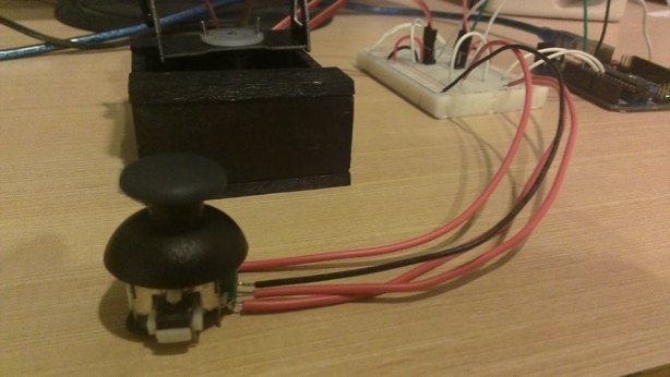
Following the end of our first year there were some very good projects made by students. This is one of the projects done by Mik(Visutr Boonnateephisit) and Nidhi Adhikari. Its a analog controlled(using a joystick)camera . Basically it can be used for security purpose, supervision and moreover due to its wide range of vision it can be used for many other desired purposes. The basic outline of the systems are as follows.

•2 servo motors are use to build the system.
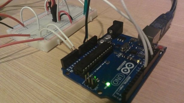
•Each signal pin of the servo motors are connected to the digital output of the arduino board.
•The thumb stick is connected to the analog input of the arduino board.
•Gears will convert motion from fast electric motor that has a low torque to a slow motion with a high torque.
•The gears will also transform motion from one shaft to another while keeping the shaft synchronized.
•The arduino is powered using an AC source.
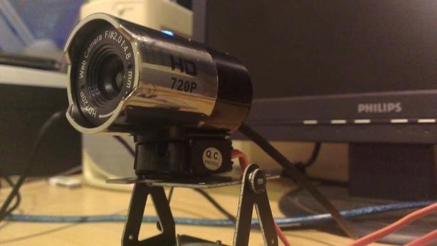
•Finally, the ptCam is connected to the computer so that it can display the video.
8553_4564604366279_773735100_n 8703_4564604886292_47861731_n 188998_4564600326178_1919182581_n 946490_4564602806240_235357108_n 983591_4564576365579_361253332_n 988920_4564575725563_1241415076_n

arduino Uno used here

arduino Uno used here

camera

camera

front look

front look

setup

setup

setup

setup

camera used in the process

camera used in the process

So, basically the joystick will act as remote control for the camera providing the directions. The torque is high enough in the system such that camera can not be manually turned by hand. The voltage required by servos can be provided with arduino. This is a very good project to do even in home and gives you enough space to play with arduino and servo actions. This was done in a neat way and looks really clean and the camera feed was good enough.The wire setup is really good and the servos are well connected with the tilt pan. Sadly the video file can not be located although we are still searching for it. In the end  a real good project pulled off by these guys. Well done guys!!!