This was the first time we dealt with making a PCB(Printed Circuit Board). It was a great experience. Now, we will share the process we used to make our simple PCB. The whole process was supervised by Chaiyaporn Silawatchananai(Tom).
Making PCB is real simple if you have these required stuffs. The materials we used and the one you will need if you want to make one are as follows.
- PCB of your desired size.( basically a copper plated board).
- Drilling tools need to put and solder the components later.
- Etch Acid(FeCl3 solution)
- Thinning Solution
- Cutter, Iron( or anything with which you can heat the plate).

back side of a plate

Copper plate
First of all we need to make a PCB layout. We did this using a software which is called Eagle(http://www.cadsoftusa.com/) . This software is pretty easy to use or you can go through some tutorials on you tube or Google and you can figure it out. After the layout is ready, it should be printed on a glossy paper. Ours was something like the one in the picture below.

Layout of PCB designed through EagleCad

PCB layout and respective size copper plate
After the printed layout is ready and we have a desired size of PCB that can fit the layout, we need to mark the layout we have in the glossy paper to the PCB. This is pretty easy as well. First heat the PCB board. We used simple Iron used to Iron clothes to do this. Anything else which is safe enough can be used as well. The main purpose is to heat the PCB.

After heating it for around 1 min(depends on the stuff you are using to heat PCB) , put the printed layout on glossy paper upside down on copper side of the PCB, as done in the picture below.

After heating and putting together glossy paper and copper plate
when the layout paper is positioned properly, heat the whole thing from above. If using Iron make sure to use different positions so that all sides of the layout is heated and gets pasted properly. Wait for another 2 minutes and use a heat-resistant gloves or any kind of grapper which will protect you from heated PCB. Dip it in water for minute or two. Now, slowly peel of the paper from the board. Be gentle here or the whole thing might be spoiled.

Dipping heated PCB stick with glossy paper in water

Peel out the glossy paper very slowly
You will see markings of your layout on the PCB. Now, clear the wet papers stuck in the PCB very gently. Make sure the markings do not get spoiled. You might not get all the markings if this is the first time dealing with PCB. We could not get it in the first time either. The markings were not clear nor were complete in the first trial. However we some what did it in the second time.
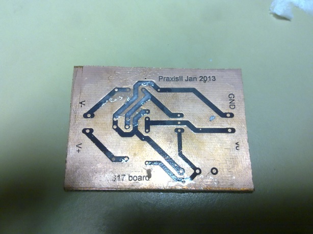
One of the perfectly formed PCB

Ours PCB missed a copper line we marked it with black marker
After the papers are cleared the PCB with markings should be dipped in the Etch Acid solution. This solution carves away the copper part in the PCB keeping the markings intact.

Using Etch Acid
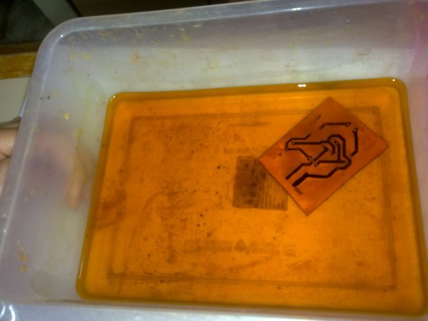
Using Etch Acid to etch out unwanted copper

Late view after using Etch Acid
You can see that the copper part is slowly getting peeled away. And after its all done , dip it in water again and there is you PCB ready .Now it needs to be cleaned so that only copper lines remain on the board. For that we used Thinning solution and slowly cleaned it. It kinda stinks so make sure to do it in some where open. After this process you will get a board with copper lines in it. Now its time to drill holes so that components can be inserted.
We used small driller made out of Dc motor and very small drill nodes. Precision is very important here as we do not want to make holes in unwanted place and in some cases outside copper lines. The holes need to be on exactly where it is supposed to be.

Drilling holes to insert components
inserting components to board

THIS IS NOT HOW YOU SHOULD INSERT COMPONENTS!
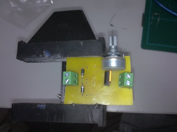
Further parts needed for the circuit like registers, transistors as per the need should be soldered in the board. And there is a PCB board ready to go!

Soldering

Soldered Backside of a PCB
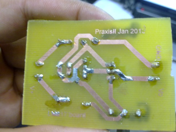
Back side of completed PCB

Our completed PCB

One of the perfected PCB made in class
This PCB could take some voltage and using potentiometer change the output from the board. Pretty handy stuff in place where you have higher source but want a lower input on components.
Good luck With making your own PCB.


